
Gridfinity Specification
This tool targets the community Gridfinity design reference, cross-checked against Gridfinity Rebuilt. This page documents the geometry generated by this application. It distinguishes fixed mating dimensions from configurable application defaults. The community reference is a draft, not a compatibility certification.
Start with the fit test before printing a large layout. The files are in millimetres with Z up. A normal export contains bins only; the visible baseplate is a preview reference. Fit Test is the exception: it includes a small printable baseplate as a separate object.
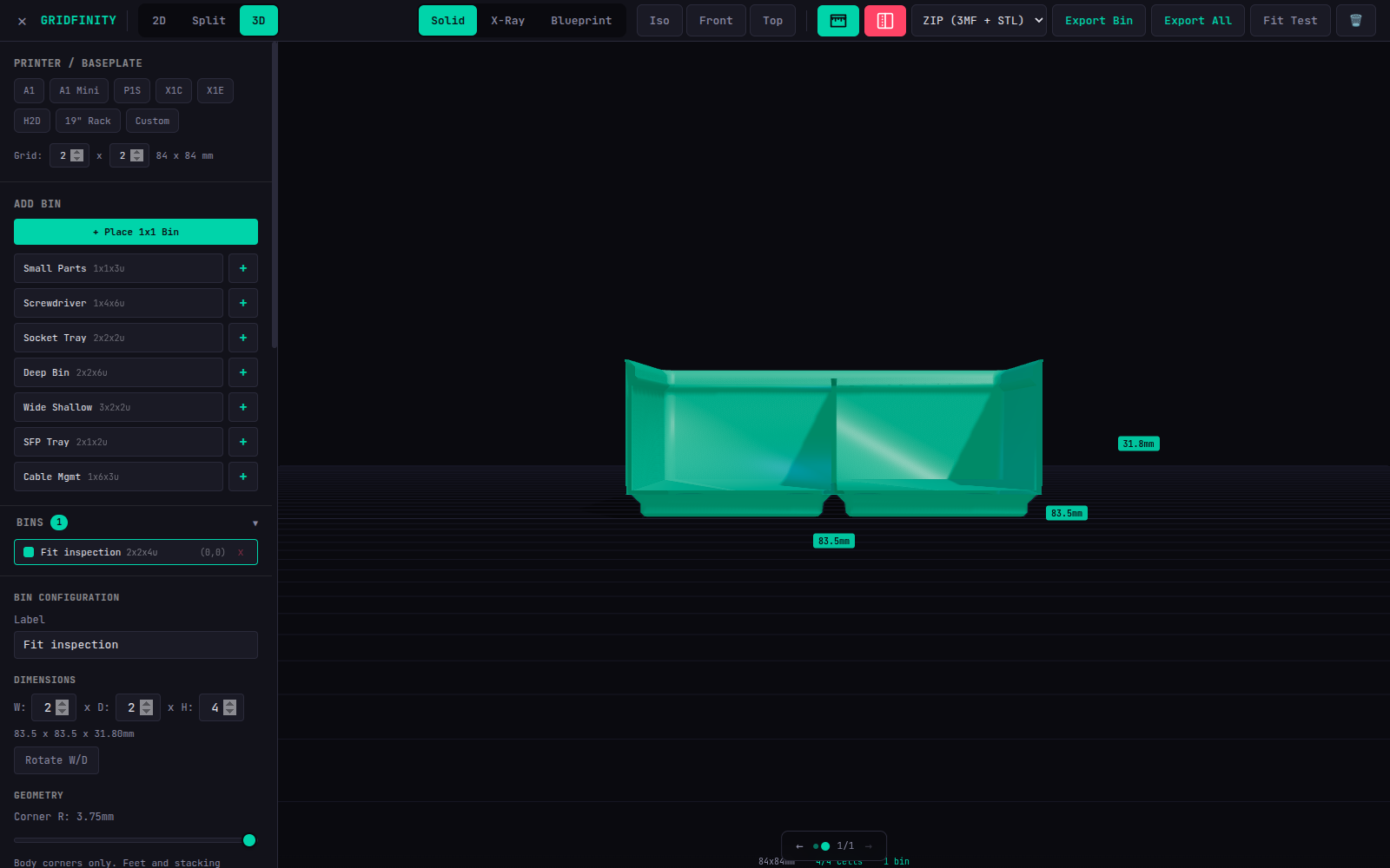
The displayed 31.8 mm height is 4 × 7 + 3.8. Section view does not alter the exported solid.
Core Dimensions
| Dimension | Value | Description |
|---|---|---|
| Cell size | 42 x 42 mm | Base unit of the grid |
| Height unit | 7 mm | One "u" of bin height |
| Perimeter clearance | 0.5 mm total | 0.25 mm per outer side; not a printer compensation setting |
| Mating foot corner radius | 3.75 mm at its top | Fixed; body corner radius can be configured separately |
| Foot height | 4.75 mm | Included in the bin's H × 7 mm height |
| Wall thickness | 1.2 mm | Configurable application default, not a fixed mating dimension |
| Bottom thickness | 0.8 mm | Configurable floor above the foot, not the full bin base height |
| Stacking lip | 3.8 mm printed | 4.4mm theoretical profile with a 0.6mm tip trim |
| Magnet holes | 6.5mm dia, 2.4mm deep | For nominal 6×2mm magnets |
| Basic baseplate | 5 mm | Open-bottom sockets, no mounting hardware |
| Screw holes | M3 (3.2mm clearance) | For screw retention |
Bin Dimensions Formula
For a bin of size W x D x H (in grid units):
| Measurement | Formula | Example (2x2x3u) |
|---|---|---|
| Outer width | W × 42mm - 0.5mm | 83.5 mm |
| Outer depth | D × 42mm - 0.5mm | 83.5 mm |
| Total height | H × 7mm (base included) | 21.00 mm |
| With stacking lip | H × 7mm + 3.8mm | 24.80 mm |
| Nominal straight-wall inner width | Outer - 2 × wall | 81.1 mm at the default wall thickness |
| Nominal straight-wall inner depth | Outer - 2 × wall | 81.1 mm at the default wall thickness |
Do not add another 4.75 mm for the feet: they are already included in H × 7 mm. Likewise, the 0.5 mm footprint reduction is applied once to the whole bin width and depth, not once per cell. A 2-cell width is 83.5 mm, not 83.0 mm.
The inner dimensions above describe the straight body walls, not the minimum opening or usable storage volume. The socket, support, label shelf, corner radii, and dividers reduce the available space. A sufficiently thick floor can fill a shallow bin while leaving its requested stacking lip present.
Z-Profile Base
Each cell has a foot following the reference profile (45° chamfers), bottom to top:
z 0.00 → 0.80   45° chamfer   width 35.60 → 37.20 mm
z 0.80 → 2.60   vertical      width 37.20 mm
z 2.60 → 4.75   45° chamfer   width 37.20 → 41.50 mm
The foot corner radius follows the inset (3.75mm at the top, 0.80mm at the bottom), so bins retain concentric mating corners. Multi-cell bins have one foot per cell at 42mm pitch, with a 0.5mm gap at the top of adjacent feet. Body corner customization does not change feet or sockets.
Magnet and Screw Recesses
Standard magnet hole centers form a 26 × 26 mm square centered in each cell (13mm from the cell center). The application's default hole is ⌀6.5 × 2.4mm for a nominal 6×2mm magnet; this dimensional allowance does not guarantee a press fit. Custom magnet inputs specify the nominal hardware size:
| Measurement | Generated value |
|---|---|
| Hole diameter | Nominal magnet diameter + 0.5 mm |
| Hole depth | Nominal magnet depth + 0.4 mm |
| M3 screw clearance | 3.2 mm diameter through the foot |
Oversized custom magnets can move the centers inward to preserve material at the foot edge, so they do not necessarily align with standard magnetized bases. Inspect large or deep recesses against the remaining wall and floor material. The basic baseplate generated by this app has no magnet pockets or screw mounting holes.
Stacking Lip
The female socket has a separate profile from the foot. Heights below are relative to the nominal rim, H × 7mm; widths are for a 1×1 bin.
| Height | Opening width | Corner radius |
|---|---|---|
| 0.0 mm | 36.3 mm | 1.15 mm |
| 0.7 mm | 37.7 mm | 1.85 mm |
| 2.5 mm | 37.7 mm | 1.85 mm |
| 3.8 mm, printed crown | 40.3 mm | 3.15 mm |
| 4.4 mm, theoretical tip | 41.5 mm | 3.75 mm |
The first and last bands are 45° chamfers, with a 1.8mm vertical band between them. The top 0.6mm is trimmed to avoid an unprintable knife edge. A separate support under the rim connects the lip to the body wall.
The 4.4 mm row describes the untrimmed construction profile only. It is not present in the exported bin; the printable lip ends at 3.8 mm above the rim.
With the upper foot bottom at the nominal rim, lateral clearance is 0.25mm per side in the straight band and 0.35mm in the chamfer bands. Ideal default bins can descend another 0.35mm to contact the inclined seat. Contact at rest is intentional; positive clearance is checked during insertion. Thick walls and internal features can affect the final resting height below the nominal rim.
Baseplate Socket
The basic baseplate uses a 42mm outline and 4mm corner radius. Its opening is 36.3mm at the bottom, 37.7mm in the straight band, and 42mm at the top. Its profile is 0.7 + 1.8 + 2.15 = 4.65mm high, with 0.35mm of relief below it in the 5mm plate. The bin foot datum is aligned with that 0.35mm relief for insertion checks.
| Height above the baseplate's bottom | Socket opening per cell |
|---|---|
| 0.00–0.35 mm | 36.3 mm, open-bottom relief |
| 1.05 mm | 37.7 mm, end of the lower chamfer |
| 2.85 mm | 37.7 mm, end of the straight band |
| 5.00 mm | 42.0 mm, top of the upper chamfer |
The plate footprint is columns × 42 mm by rows × 42 mm, without the bin's 0.5 mm perimeter reduction. In an assembly the bin foot begins 0.35 mm above the plate bottom. In a print file each independent part sits at Z=0; the fit kit separates the plate and bins rather than exporting an assembled overlap.
What has been verified
Automated checks use independently tabulated sections, a 0.15mm expanded foot envelope, multiple bin sizes, and meshes reconstructed from the actual 3MF ZIP/XML. These verify nominal geometry; they cannot measure printer calibration or warping.
The verification record identifies the executed tests. There is no physical-fit certification, independent 3MF format validator, or automated slicer-import test at present. Printer presets select a layout grid, not a machine configuration. See export validation and printer presets for those boundaries.